 Deutsch
ROVER 3 hp
Technology
1904 - 1906
In the case of early motor vehicles, the technology is described very precisely and in great detail. Since vehicle manufacturers are experimenting with many components, the description is a source of pride in their own development spirit - and of course in the results. For the Imperial Rover 3 h.p. motorcycle ROVER goes into detail on some components.
The Motor
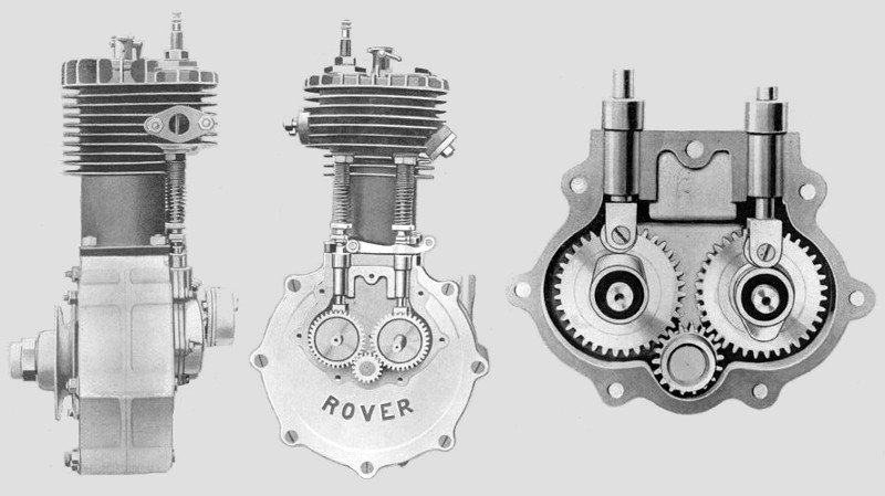
The Imperial ROVER Motors are distinguished by the following points:
- The flywheels of the Motor are constructed to carry a very largely preponderating share of their weight close to their peripheries.
- The main bearings are both large in diameter and long, that on the belt side of the engine being extended to an exceptional length by the use of a deeply dished driving pulley.
- An improved and patented method of retaining the valve springs is employed, consisting of a slotted collar, which slides on to a reduced diameter near the end of the valve stem, over which a sleeve fits, holding it in its place; the top of the sleeve is cupped out to accommodate the lower end of the valve spring.
- Both valves being interchangeable, only one spare valve need be carried.
- The sparking plug is situated immediately above the inlet valve, where it is subjected to the scouring influence of the inrushing gas.
- In the centre of the cylinder head is inserted a paraffin valve of a special design, conveniently opened for use, but doubly provided against leakage.
The objectionable self-acting inlet valve which was always a cause of so much trouble has been done away with, and both the inlet and exhaust valves are operated by identical mechanical means, a separare cam being used for each valve, and the lower end of each valve tappet being provided with a roller to minimize the friction. An improved and protected method of retaining the valve springs is employed, consisting of a slotted collar which slides on to a reduced diameter near the end of the valve stem, over which a sleeve fits holding it in its olace; the top of the sleeve is cupped out to accomodate the lower end of the valve spring. Both valves being interchangeable, only one spare valve need be carried.
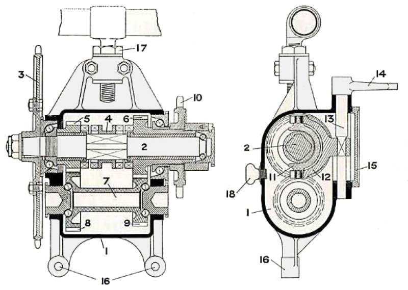
The ROVER Two-Speed Gear
| Legend | |||
|---|---|---|---|
| 1 | Casing for Two-speed Gear | 10 | Chain Pinion |
| 2 | Main Shaft | 11 | Slipper for Moving Clutch |
| 3 | Chain Sprocket | 12 | Forged Lever for Moving Clutch |
| 4 | Double Claw Clutch | 13 | Rocking Shaft for Forked Lever |
| 5 | Low Speed Pinion | 14 | Lever for Rocking Shaft |
| 6 | High Speed Pinion | 15 | Cover for Inspection Hole in Case |
| 7 | Back Shaft | 16 | Lugs for attaching Case to Frame of Machine |
| 8 | Large Gear Wheel on Back Shaft | 17 | Nut for adjusting Chains |
| 9 | Small Gear Wheel on Back Shaft | 18 | Oil Plug for Case |
The Two-speed Gear is contained in an oil-tight case (1), arranged between the engine and the back road wheel; it consists of a shaft (2), to one end of which is keyed a chain sprocket (3), which is connected by a roller chain to the engine clutch. In the centre of the shaft is a squared portion on which is mounted a sliding double claw clutch (4). At one end of the shaft is a small spur gear (5), and at the other end the larger spur gear (6), both of which are capable of revolving independently on the shaft, but, by means of the claw clutch, either can be locked to the shaft when desired. At the rear of the shaft and parallel with it is another shaft (7), with the spur gears (8) and (9) cut on the ends of it, and arranged in mesh with the spur gears previously mentioned. The spur gear (6) has an extended boss projecting through the case on the side opposite to the chain sprocket (3), and on this boss is secured the chain pinion (10), which transmits power to the road wheel. The two shafts are carried on ball bearings, and the sliding clutch (4) is operated by a slipper (11) and forked lever (12), carried on the rocking shaft (13), which can be moved by a lever (14), fixed on its outer end; this lever being coupled by a rod to a hand lever on the top tube of the machine. When the clutch (4) is in engagement with the low gear (5), the motion of the square shaft (2) is transmitted to the chain pinion (I0) through the reducing gear on the back shaft (7), whilst, if the clutch is in engagement with the high gear (6), it locks the chain pinion to the square shaft and gives a direct drive for the high gear.
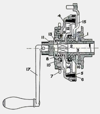
The ROVER Free Wheel Clutch
| Legend | |
|---|---|
| 1 | Side of crank case |
| 2 | Crankshaft |
| 3 | Bearing with square thread |
| 4 | Body of Clutch |
| 5 | Fibre ring |
| 6 | Retaining plate for fibre ring |
| 7 | Chain pinion |
| 8 | Ball race |
| 9 | Fixed cone for ball bearing |
| 10 | Adjusting cone lor ball bearing |
| 11 | Nut holding clutch on crankshaft |
| 12 | Sliding cone |
| 13 | Clutch spring |
| 14 | Cup for ball thrust bearing |
| 15 | Releasing lever for clutch |
| 16 | Adjusting cone for thrust bearing |
| 17 | Starting handle |
An outer member (4) is carried on a ball hearing on one end of the crankshaft (2); to this is fixed a chain pinion (7) for transmitting the power to the road wheels. The outer member contains a fibre friction ring (5). A conical disc (12) is arranged to slide on a squared portion of the crankshaft and is normally forced into engagement with the fibre ring by means of a spiral spring (13), thus coupling the chain pinion to the crankshaft. On the outer side of the crankshaft bearing (3) is a square thread fitting a corresponding thread in the boss of a lever (15); a ball thrust bearing is arranged between the boss of this lever and the inner face oi the conical disc. When it is desired to disconnect the engine from the motion of the machine or vice versa, the lever is partially revolved on the square thread, by means of a hand or a foot lever, thus forcing the cone, against the pressure of the spring, out of engagement with the fibre of the ring. By this arrangement we obtain an efficient clutch devoid of all end thrust and friction when driving, and which runs freely on ball bearings when out of action.
The Contact Breaker
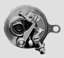
The contact-breaker is quite an original design, having neither a trembler blade nor a platinum tipped screw; it is a „wipe“ contact, and yet there is no friction whatever except at the moment of the contact being made. The way this combination of desirable features is achieved is by substituting for the usual trembler blade a rocking lever having a projection near its middle to meet the projection on the revolving cam; as the cam turns round these two projections are rubbed or wiped together, making and breaking contact, and effectually preventing a deposit of gummy oil, but the moment the projections part the locking lever is pushed by a compression spring against the end od a screw formng a stop which prevents the lever remaining in contact with the cam. Thus the advantages of the wiping contact are secured, free from the constant friction which takes place with the common systems of wipe or brush contacts; the sudden intervention of the stop ensures a quick „break“, resulting in a hot and fat spark between the extremities of the sparking plug. This design is also protected.
The Electrical System
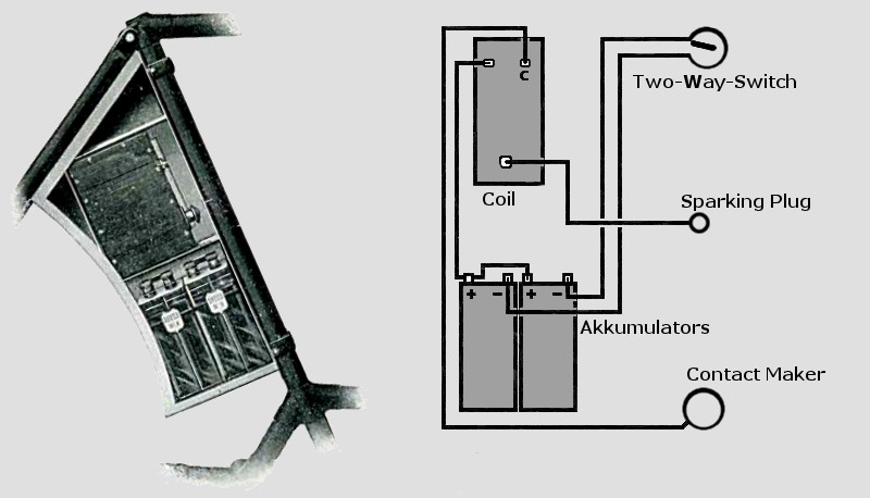
To avoid the annoyance so frequently experienced by the discovery that an accumulator has run down below the limit of effectiveness, the IMPERIAL ROVER motor cycle is fitted with two separate accumulators, which are wired up to a two-way switch fitted on the handlebar. The terminals on the switch are marked one and two, and the accumulators are numbered to correspond. Thus, one accumulator can be always held in reserve and instantaneously switched into use upon the other evincing signs ol exhaustion.
The coil is the highest class trembler coil, contained in the upper compartment of the same case as the aocumulators. A diagram representing the system of wiring is shown.
The Tool Bag
Without a doubt, in these years - a workshop network is still under construction - a complete tool kit is part of the necessary technology of a motorcycle. And ROVER provides a complete set.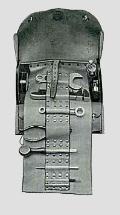
The Special Tool Bag, with loose flap, contains the following indispensable accessories:
• One repairing outfit• One large adjusting wrench
• One cone spanner
• One box spanner
• One adjustable peg spanner
• One pair of cutting pliers
• One valve complete
• One can for paraffin
• One can for lubricating oil
• One screw driver
• One belt punch
• One taper punch
• One belt fastener
• One valve extractor
And an assortment of bolts, nuts, washers, splitt pins, etc.
METEOR Adjustable Wrench
In addition, an adjustable open-end wrench - patented by J. K. Starley - is offered for sale:
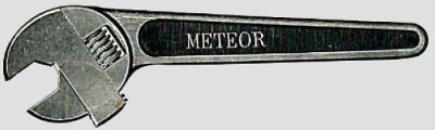
Made in three sizes, suitable for Cycles, Motor Cycles and Cars. This spanner is very carefully machined and fitted, being strengthened by the special shape of the sliding piece, and made throughout from best steel stampings. A most serviceable addition to any Motor outfit.
Prices: Cycles 3/- | Motor Cycle 7/6 | Motor Car 12/6
© 2021-2026 by ROVER - Passion / Michael-Peter Börsig