 Deutsch
ROVER Motorcycles
Motorcycle Dictionary
1902 - 1926
Around 1910, the range of motorbikes increases enormously. ROVER also enters the scene again. Therefore, technicians and specialist journalists start thinking about which motorbike should be regarded as "ideal".
We have included this ideal illustration on our website, as it is fictitious but very explanatory and also reproduces the component names that have been forgotten today - quasi a journey back in time over 100 years.
We also reproduce the original article on the illustrations.
Source: Magazine name and exact publication date are not known.
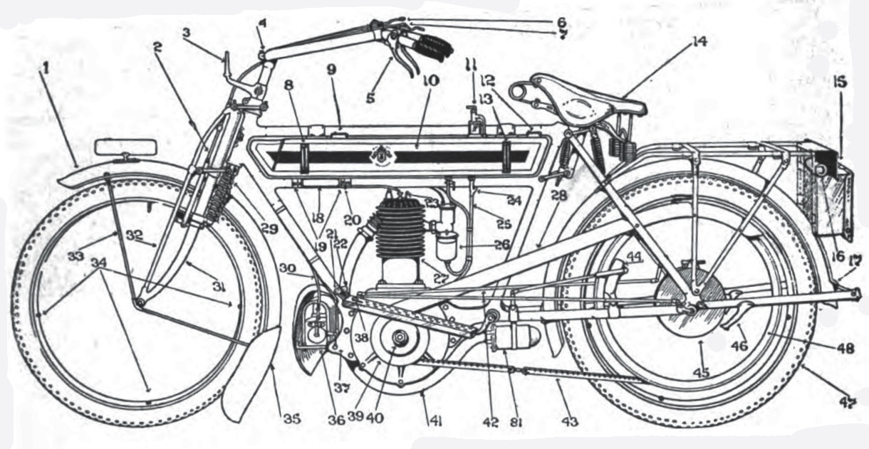
| No. | Explanation | No. | Explanation |
|---|---|---|---|
| 1 | Front extension mudguard | 42 | Rods from pedals on footboard to high and low gears |
| 2 | Front brake band | 43 | Driving belt |
| 3 | Lamp Bracket | 44 | Rear belt rim brake |
| 4 | Adjusting clip for handlebar rake | 45 | Casing of two-speed gear |
| 5 | Front brake lever | 46 | Stay for stand |
| 6 | Throttle lever | 47 | Rear studded tire |
| 7 | Air lever for carbureter | 48 | Belt rim |
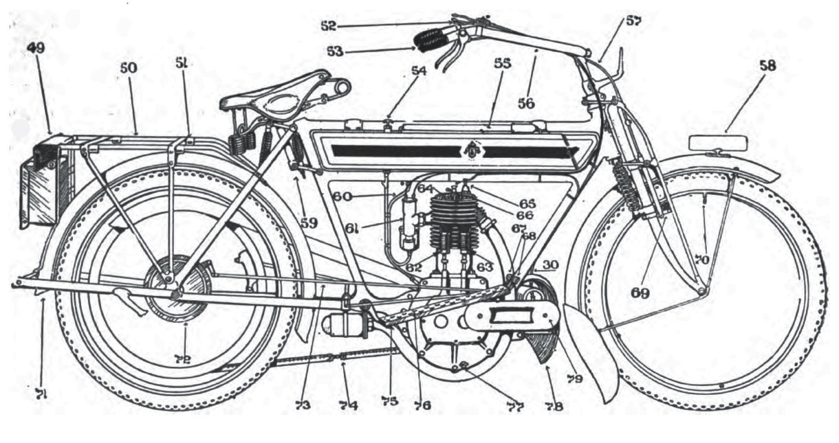
| 8 | Gasoline gauge | 49 | Rear number plate |
| 9 | Gasoline filler cap | 50 | Luggage carrier |
| 10 | Gasoline tank | 51 | Eyes for straps of luggage carrier |
| 11 | Drip-feed lubricator | 52 | Magneto control lever |
| 12 | Filler for oil tank | 53 | Magneto switch |
| 13 | Oil gauge | 54 | Hand pump lubricator |
| 14 | Touring saddle | 55 | Tire inflator |
| 15 | Tool kit | 56 | Adjustable handlebars |
| 16 | Oilcan | 57 | Cable connection from 5 to front rim brake 60 |
| 17 | Clip for stand on mudguard | 58 | Front number plate |
| 18 | Paraffin reservoir | 59 | Spring saddle pillar |
| 19 | Clips for paraffin reservoir | 60 | Gasoline pipe |
| 20 | Tap for paraffin reservoir | 61 | Mixture chamber of carbureter |
| 21 | Top gear lever | 62 | Exhaust valve spring |
| 22 | Low gear lever | 63 | Inlet valve spring |
| 23 | Compression release tap | 64 | Cap over exhaust valve |
| 24 | Union from the oil pump and side feed drip | 65 | Sparking plug |
| 25 | Oil | 66 | Cap over inlet valve |
| 26 | Float chamber of carbureter | 67 | Pedal to actuate rear rim brake at 44 |
| 27 | Air-cooled cylinder | 68 | Pedal to actuate internal-expansion brake at 72 |
| 28 | Belt guard | 69 | Front rim brake block |
| 29 | Front fork springs | 70 | Tire-inflating valve |
| 30 | Switch wire between magneto and handlebar at 53 | 71 | Rear mudguard |
| 31 | Main front forks | 72 | Rear internal-expanding brake |
| 32 | Auxiliary front fork | 73 | Connecting rod from pedal 67 to brake 72 |
| 33 | Front guard stay | 74 | Adjustable belt fastener |
| 34 | Tyre securing bolts | 75 | Aluminium footboard |
| 35 | Mudguard splasher | 76 | Rubber studs in Aluminium footboard |
| 36 | Magneto | 77 | Oil drainage tap from crankcase |
| 37 | Cradle for engine | 78 | Mudguard for magneto |
| 38 | Locking and release pedal for high gear | 79 | Dust-tight cover over magneto driving gear |
| 39 | Crankcase | 80 | Studded front tire |
| 40 | Nut for handle starting of engine | 81 | Muffler |
| 41 | Exhaust pipe |
Here follows the article that accompanied the illustrations:
For Novice And Expert Too
Motorcycles As They Are and May Be - Their Parts Illustrated
We are indebted to London Motorcycling for the two drawings and the descriptions which are published on these two pages. The illustrations and the matter accompanying them have been arranged to embody the latest ideas of motorcycle construction, although, of course, this machine exists only in the imagination of the designer. Many of its features differ from what is generally accepted as regular design, but are, nevertheless, methods that we believe will be fairly universal in the near future and we thereforee have no hesitation about including them in this very up-to-date machine. For instance the oil hand-pump (No. 54) is at the rear of the tank, ant its corresponding gauge (No. 13) is also at the rear. The driving belt has above it a really sunstantial guard and is so arranged that it can be dismantled by removing four screws. The exhaust pipe is brought down in a big sweep beneath the crankcase and taken to the space between the engine and mudguard, where a muffler worthy of the name can be fitted. These drawings are designed to educate the beginner at the sport; but the expert, in going through the details, may wonder where the exhaust cut-out is fitted. It is nor shown anywhere on the drawing, for the good and sufficient reason that it is a nuisance to every other user of the highway.
The designer avoided the twisting of the copper gasolene pipe into curls, by clamping it with detachable clips to the oil pipe, each bracing up the other without interfering with dismantlements when necessary, and making both actually stronger than where curls are employed. Another innovation is a rear internal-expansion brake, or, rather, the use of this, together with a rear-belt rim brake. The designs show both, because they are typical of 1910 practice; but, of course, only one of these would be necessary for the rear wheel. The fillers to the gasolene and oil tanks are much larger than is usual, and have spring-held caps that need not be unscrewed, hinges holding them when the lids are pulled up. A paraffin injector is shown at No. 18, with tap (No. 20) and pipe leading directly over the mouth of the compression-release tap (No. 23).
Every part has been drawn with due reference to its surroundings, and, although not actually to scale, it is sufficiently near to accuracy to form a basis from which good working drawings might be evolved. Most manufacturers are on the alert for good ideas, and are as keen to satisfy the demand for the best that human brains can device. These drawings are designed to help in that direction.
It may be useful to compare some of the fittings on this machine with those at present, or about to be, constructed. One of the small, but none the less important requirements, now the magneto ignition is almost universal, is a proper switch arrangement for earthing (short-circuiting) the current, and accessory makers have realized this fact and can now supply such a fitting. This arrangement should form an integral portion of the machine. If the drawing on the second page is carefully examined it will be noticed that the wire from the front central terminal of the magneto is taken up above, clipped to the frame, and passing thence past the handlebar is taken through near the end, and there finished off by a projecting spring-pushed button at the end of the right-hand grip, convenient for touching with one finger, without nterfering with the proper control of the exhaust lifter by the rider’s right hand. This detail is referred to particularly in order to emphasize the fact that these drawings have occupied much time in considering every likely point that can arise.
Readers are advised to keep both reproductions for future reference, because from time to time we purpose publishing special articles dealing with various phases of the subject from the points of view both of the novice and the expert. The latter may cavil at the omission of a pedaling chain from the design; but this has been done by the designer because of his conviction that, except for lightweights, the pedaling chains will have to go the way of the exhaust cut-out - into the limbo of the unregretted. Some indications of this trend will be found in the number of machines to be fitted with free engines and two-speed gears. This will be the standard type of the future, and we shall be very much mistaken if the 1911 Show does not reveal these in preponderating numbers.
The only point upon which there may be some difference of opinion concerning the merit of our design is the capacity of the tank, though it is the ideal pattern for a big mileage.
© 2021-2026 by ROVER - Passion / Michael-Peter Börsig