| |  View of the robust, clean construction of the ROVER "PILOT" engine (left engine side). |
|
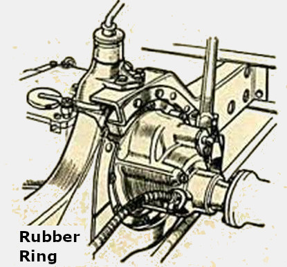 Mounting of the engine in a rubber ring |
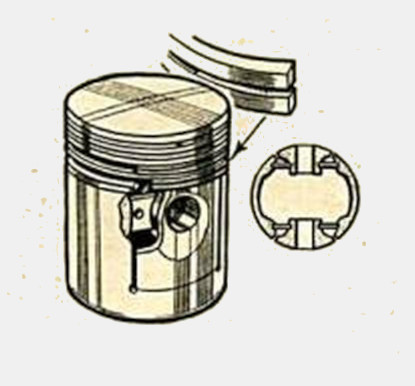 Piston with two sealing and two wiping rings |
 The pedals are easily adjustable in position and reach |
|
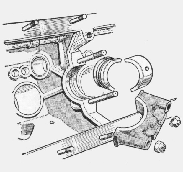 Assembly of the crankshaft bearings |
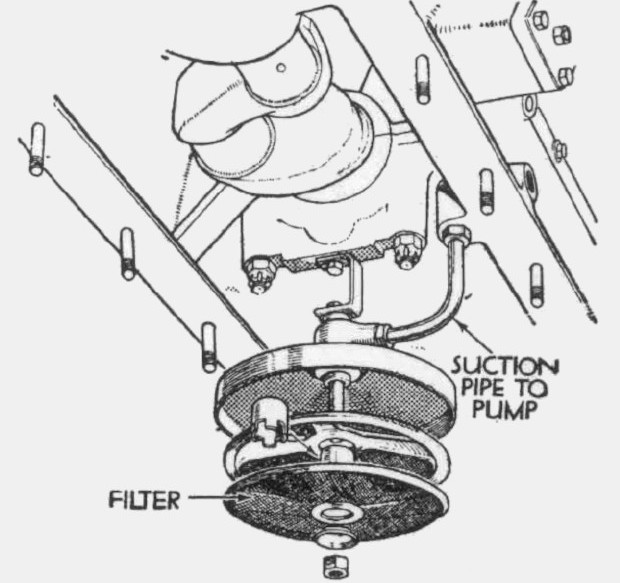 The oil filter in the oil sump |
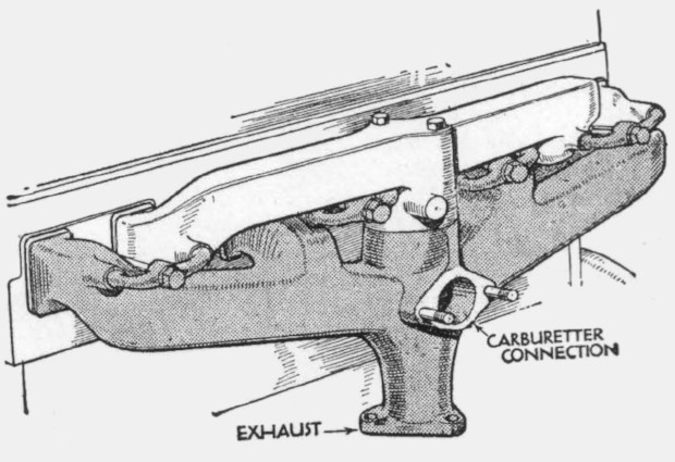 Intake and exhaust manifolds lie inside and above each other |
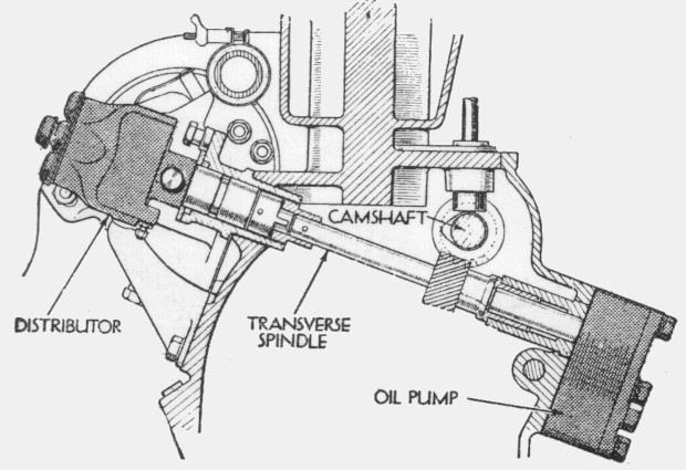 The distributor and the oil pump are driven by a spindle driven by the camshaft |
|
 Chassis Rover 'Pilot' 12hp, Model year 1932
The new Rover chassis is a fine example of the small six-cylinder class. Among the features shown in this drawing are the beautifully designed engine with overhead valves with tandem drive for dynamo and water pump, the four-speed transmission, the closed cardan shaft and the bottom worm drive. The rear axle suspension system, the position of the tank in the rear and the tool tray in the scuttle in front of the transverse bulkhead should also be noted.
Note:The drawing has been assembled from two parts and partially completed. |
 Rover 'Pilot' 14hp, Model year 1933
The view into the 'Pilot' 14hp of the model year 1933 clearly shows the changes compared to the model year 1932: The rear axle is now guided by semi-elliptic springs (so-called 'underslung' suspension). This allows an overall flatter body than in the previous year. Therefore the inner floor is no longer completely flat, but a central arched floor has become necessary to accommodate the transmission. |
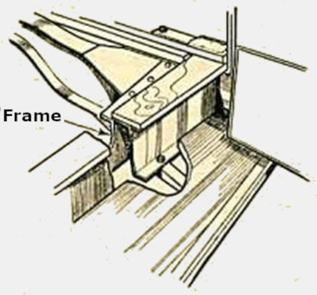 The body is mounted on a subframe |
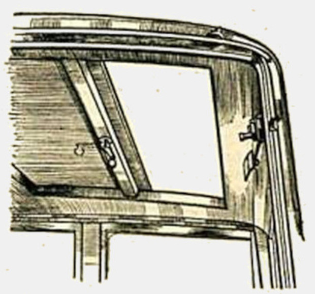 The sunroof can be locked in any position by a lever movement |
|
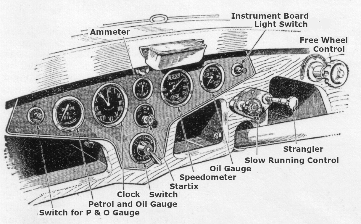 |
The dashboard of the 1933 model year |
 Deutsch